As the industry replaces mechanical relays with solid-state switches in high current motor control applications, intelligent gate drivers from the FLEXMOS™ portfolio allow pairing with external MOSFETs. Enabling scalable design flexibility for varying load requirements, onsemi pre-driver solutions can scale motor drive applications from a single motor to as many as seven, making these products ideal for a wide range of automotive body electronics applications.
The primary functions of the pre-driver IC are the following:
- Interfaces between the microcontroller (uC) and the external power MOSFET output stages. The pre-driver IC provides isolation between the microcontroller low voltage domain (typically less than 5.5 volts) and the 40 volts maximum seen on an automotive battery-connected system.
- Provide the gate overdrive for the high side stages to allow the use of N-channel MOSFETs.
- Increases the robustness and diagnostic capability of the system by monitoring and protecting the external MOSFET and the connected load.
- Provide specific AC characteristics for turn-on and off profiles to minimize electromagnetic emissions and power loss efficiency for switching applications.
Applications that require bi-directional motor rotation use external MOSFET H-Bridge configurations—integrated H-Bridges for their simplicity. In contrast, applications with greater importance on thermal management and higher load current requirements use pre-driver and external MOSFET solutions. Since the power dissipation of the pre-drivers is much more manageable with higher channel counts, the global system response dramatically improves as the number of high current motors increases in a system. A single gate driver IC, such as the NCV754x, can monitor all the half-bridge nodes and the connected loads and prevent unintentional motor movements due to faulted conditions.
The H-Bridge configuration allows the engineer to direct the current flow in the motor, shown in Figure 1. The direction of the current dictates the direction the motor spins.
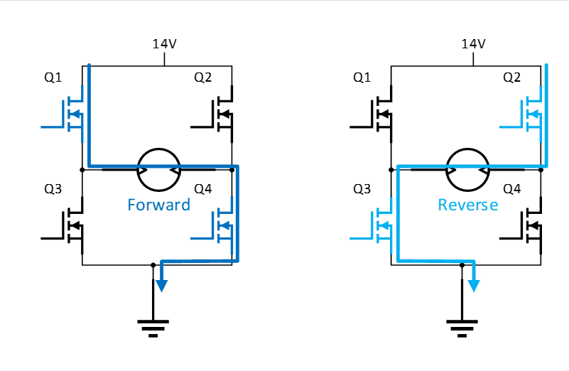
Figure 1: H-Bridge Motor Control
The amount of current flowing through the motor directly correlates to the motor speed and the available torque. If the current in the motor increases, then the speed of the motor will increase if the external load’s torque requirements remain constant. Alternatively, the increased current can translate to higher torque for heavy loads while maintaining a constant speed.
The FLEXMOS pre-drivers from onsemi have programmable current sources and calibration techniques, allowing the system designers to choose from our extensive portfolio of N-channel MOSFETs offered in the Application Specific Standard Product (ASSP) market. The MOSFET Product Recommendation Tool can be used to select the appropriate MOSFET for the suitable application.
The pre-driver topology offers a faster design cycle to meet the changing system requirements based on different automotive OEM specifications, trim levels, and model types.
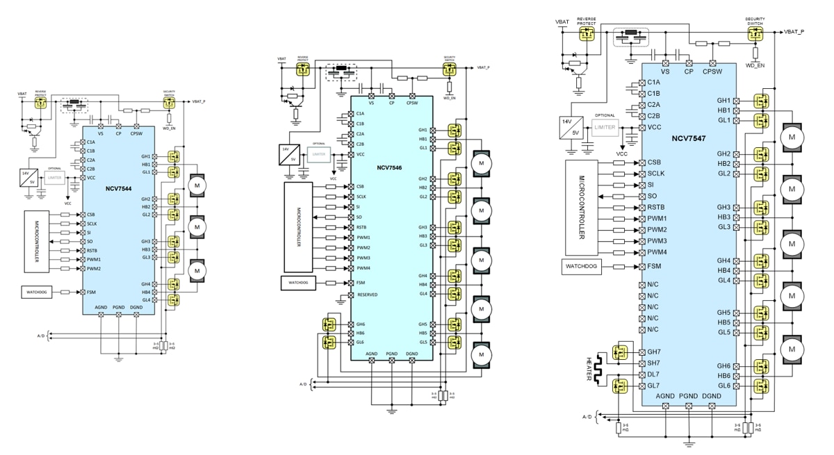
Figure 2: NCV754x Application Diagram
The shorter design cycle is achievable by allowing the system designer to scale the MOS power stages for the different loads while keeping the remaining hardware components the same. Minor software modifications are needed to fine-tune the controls of the new MOSFETs while maintaining the overall software flow. As seen from Figure 3, the IP re-use for the software development is more pronounced when choosing the pre-driver solution from the same product family. onsemi has the following gate driver devices which share the same SPI register settings and programmability:
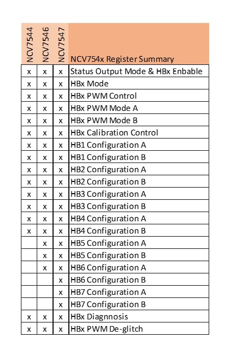
Figure 3: NCV754x Register Summary
The system designer can optimize cost savings with multiple pre-driver options through different channel combinations to implement the number of motor actuators required in the OEM specification. A variety of end applications can use the devices due to the flexibility of the pre-drivers, including:
- Seat control modules
- Door locks and latches
- Liftgate actuators
- Sunroof or moonroof actuators
- Window lifters
The half-bridge driver block has multiple programmable pull-up and pull-down current sources to charge the gate of the external MOSFET. Figure 4 illustrates a simplified view of the half-bridge pre-drivers configured with external MOSFETs and a motor load.
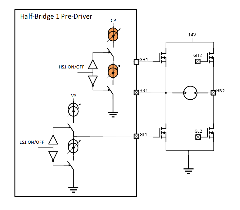
Figure 4: Simplified HB Pre-Driver Controlling External MOSFETs and Motor Load
The programmable current sources highlighted in orange in the figure above enable advanced slew rate control. For a faster turn-on behavior, the HS1 pull-up current source can be increased in stages to charge the gate faster, resulting in predictable switching behavior for the motor loads. The significant benefits of precise slew rate control are enabling higher pulse width modulation (PWM) frequency with tighter minimum and maximum duty cycles and managing the power loss versus reduced electromagnetic emissions.
For motor control applications, it is highly desirable to have PWM above 20 kHz to be above the audible frequency range. The better performance on the duty cycle minimum and maximum values offer advanced speed control of the motor load with varying torque requirements. For example, for heavy loads or motor start conditions, higher torque is needed to keep the speed constant. The system designer must increase the duty cycle to increase the motor’s current flow to achieve higher torque. Thus, operating at a duty cycle closer to the 100% value is desirable.
The power loss of MOSFETs is maximum when the channel starts to conduct due to the high current and high drain-source voltage (VDS) operating point. Often it is desirable to quickly transition from a high VDS state to the fully enhanced VDS stage of the MOSFET. Thus, minimizing the switching losses during the PWM cycles for demanding loads. Switching too quickly can result in shoot-through events that can cause degradation of the modules or undesirable electromagnetic emissions from the system. The selectable current sources for the gate driver stage allow the system designer to modify the switching profile based on thermal or emission needs during design validation, end of line calibration in the production phases, and even for software updates during an end product’s lifetime.
In addition to MOSFET control, the FLEXMOS half-bridge pre-drivers monitor and protect the external MOSFETs and the connected load in the event of a short circuit by monitoring the VDS of the active MOSFETs. Figure 5 shows an example of the output waveform and the various fault conditions. Selected FLEXMOS pre-drivers offer the VDS monitoring scheme in two separate segments: dynamic VDS protection and static VDS protection. The dynamic VDS protection monitors the switching phase while the static VDS protection is active when the MOSFETs are fully on. For a known voltage versus time switching profile programmed at the factory line, the selected FLEXMOS half-bridge devices can monitor the progression of the output voltage (VHB) and determine if there is a fault condition.
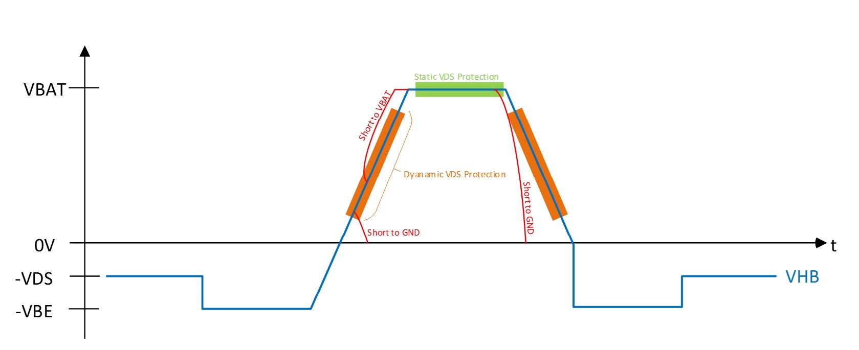
Figure 5: Half-Bridge Output Switch Profile and VDS Protection
For in-depth information on the programmable current settings, PWM operations, and device protection features, please refer to our application note - MOSFET Gate Drive Requirements and Initial Parameter Set Solution with the NCV7544, NCV7546, and NCV7547 Half-bridge Pre-drivers (AND90124/D) and reference tools. Please request the evaluation fixtures for rapid bench evaluation via the onsemi sales team.
Addtional design resources: